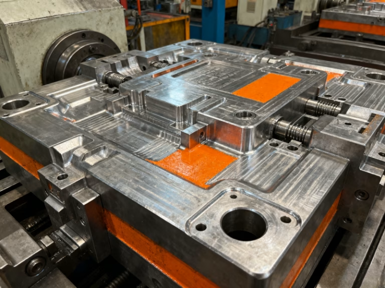
Wall thickness affects how an injection-molded part fills, packs, cools, shrinks, and carries load. The best starting point is not one universal number. Choose a nominal wall for the exact resin grade and part requirements, keep it as uniform as practical, and treat every thick or thin exception as a feature that must be reviewed. This injection molding wall thickness guide explains the screening ranges, design decisions, defect risks, and validation steps you should address before tooling release.
Injection Molding Wall Thickness Quick Answer
For many conventional thermoplastic parts, an early design study often begins within a broad range of about 1 to 4 mm (approximately 0.04 to 0.16 in). That range is not a manufacturing specification. Some high-flow resins and small parts can use thinner walls, while large parts, structural sections, optical parts, and specialty materials may need a different approach.
Use this sequence instead of selecting a thickness from a generic chart:
- Define the load, stiffness, impact, appearance, temperature, chemical, electrical, and assembly requirements.
- Select the exact resin grade or a short list of qualified candidates.
- Establish a nominal wall that the material can fill across the required flow length.
- Keep walls uniform and replace solid thick sections with cores, ribs, curves, or gussets where practical.
- Identify unavoidable thickness transitions, intersections, cosmetic zones, and critical dimensions.
- Validate the design with material data, DFM review, appropriate flow and cooling analysis, and representative molded parts.
The correct result is a documented wall-thickness strategy, not a single number copied into every feature.
What Does Nominal Wall Thickness Mean?
Nominal wall thickness is the primary or reference thickness used across the main shell of a molded part. It gives designers, mold engineers, and material specialists a common basis for evaluating flow, cooling, ribs, bosses, radii, draft, gates, and local deviations.
A housing may have a 2.0 mm nominal wall, for example, while its ribs, bosses, edge returns, sealing lands, and attachment features use other dimensions. The 2.0 mm value does not automatically make those features acceptable. Their intersections may create a much larger local mass even when each individual dimension looks reasonable.
Create a thickness map before requesting tooling. Mark:
- the nominal wall;
- all intentionally thin or thick regions;
- transitions between thicknesses;
- rib, gusset, and boss intersections;
- corners, steps, and deep pockets;
- cosmetic surfaces opposite heavy features;
- long flow paths and last-to-fill areas;
- dimensions that control fit or sealing.
This map turns wall thickness into a reviewable design decision and makes DFM comments easier to resolve.
What Wall Thickness Should You Use for Common Resins?
The following ranges are useful only for early screening. The inch values are published design-planning examples, with approximate metric conversions rounded to one decimal place. They are not universal limits for a resin family. They do not replace the data sheet for the proposed grade or a review of part size, flow length, gate location, reinforcement, texture, color, loading, or molding conditions.
| Resin family | Early screening range | Important qualification |
|---|---|---|
| ABS | 1.1–3.6 mm (0.045–0.140 in) | Grade viscosity, cosmetic class, impact and flame requirements can change the choice |
| Acetal or POM | 0.8–3.0 mm (0.030–0.120 in) | Long flow paths and thick masses need material-specific review |
| Nylon or PA | 0.8–2.9 mm (0.030–0.115 in) | Moisture, reinforcement, flow direction and conditioning affect performance |
| Polycarbonate or PC | 1.0–3.8 mm (0.040–0.150 in) | Optical, impact, stress and processing requirements may need a specialized design |
| Polyethylene or PE | 0.8–5.1 mm (0.030–0.200 in) | Density, shrinkage and stiffness differ substantially by grade |
| Polypropylene or PP | 0.6–3.8 mm (0.025–0.150 in) | Living hinges, long-term creep and shrinkage require separate evaluation |
| Polystyrene or PS | 0.9–3.8 mm (0.035–0.150 in) | Impact-modified grades and cosmetic requirements can shift the range |
| Polyphenylene sulfide or PPS | 0.5–4.6 mm (0.020–0.180 in) | Reinforcement, flow orientation and high-temperature requirements are grade-specific |
Do not interpret the lower end as a guaranteed minimum or the upper end as an approved maximum. A small connector made from a high-flow grade and a large enclosure made from the same resin family do not have the same filling conditions. Likewise, a value that molds successfully may still fail stiffness, impact, creep, flammability, dielectric, optical, or dimensional requirements.
If the exact resin has not been selected, compare the actual grade-specific recommendations with the required geometry. An overlap can help define an initial study window, but does not prove that the part will fill or perform. Keep the decision provisional until the material and molding conditions are reviewed.
Why Does Uniform Wall Thickness Matter?
Uniform wall thickness gives the melt and the cooling system a more predictable job. Variations affect several stages of the molding cycle.
Filling
Molten polymer generally flows more easily through a thicker section than through a thinner one. A sudden increase in thickness can attract flow and create race tracking, while a thin branch may hesitate or freeze before the rest of the cavity fills. These effects can move weld lines, change air-trap locations, or increase the pressure needed to reach the end of fill.
Packing
After the cavity fills, holding pressure supplies additional material as the polymer contracts. A thin region between the gate and a thick region may freeze early and block effective packing of the heavier section. The thick section can then shrink without enough compensation, increasing the risk of sink or an internal void.
Cooling
Thick sections retain heat longer than thin sections. When adjacent regions cool at different rates, they develop different shrinkage histories and residual stresses. The result may be warpage, dimensional drift, visible sink, or a longer cycle before safe ejection.
Structural Performance
Thickness changes also alter stiffness and stress distribution. A sharp step can create a stress concentration, while a heavy intersection may become dimensionally unstable. Uniformity does not guarantee strength, but it helps separate functional loading decisions from avoidable molding variation.
Uniform does not mean every point must have an identical measurement. It means variations are intentional, gradual where practical, and supported by material, flow, cooling, appearance, and structural requirements.
How Do You Choose the Nominal Wall Thickness?
Start With Function Instead of a Molding Average
List what the part must do before selecting a number. Include load direction, allowable deflection, impact, service life, creep, temperature, chemicals, UV exposure, moisture, electrical needs, flame requirements, sealing, fastening, and assembly forces. Mark which surfaces must remain flat and which areas are cosmetic.
If a wall is sized only from molding convenience, it may not meet the application. If it is sized only from a static strength calculation, it may be difficult to fill, slow to cool, or prone to sink.
Use the Exact Resin Grade
Material-family names are too broad for a final decision. Melt flow, fillers, fiber length, shrinkage, crystallinity, moisture sensitivity, impact modification, flame retardants, and color packages can change processing and performance. Ask for the current grade data and processing guidance rather than assuming that all ABS, nylon, PC, or PP behaves alike.
For reinforced materials, consider orientation. Fibers align with flow and can produce different shrinkage and mechanical properties in different directions. Changing wall thickness or gate location can therefore change both the fill pattern and the final part behavior.
Check Flow Length and Gate Strategy
Wall thickness cannot be evaluated without the distance the melt must travel. A thin wall close to a gate may fill reliably, while the same thickness at the end of a long, branched flow path may not. Gate type, gate size, runner design, venting, mold temperature, melt temperature, injection speed, and machine response also affect the result.
Identify the ratio of flow length to wall thickness for the proposed material and geometry. Treat supplier flow data as comparative test information, not a direct promise for your part. Complex cavities, abrupt thickness changes, textured surfaces, inserts, and multiple flow fronts require additional review.
Balance Appearance and Dimensional Requirements
Cosmetic surfaces make local thickness especially important. A rib or boss behind a glossy wall can create a visible sink even when the part remains functional. Texture and color affect how easily a depression or flow variation can be seen. Critical flatness or sealing surfaces may also be sensitive to uneven cooling.
Create an appearance map and keep heavy intersections away from the most visible surfaces where possible. Define how appearance will be approved: lighting, viewing angle, distance, texture reference, color standard, and sample limit.
Keep Assembly Features in the Same Review
Screw bosses, inserts, snap fits, seals, bearings, and welded joints often drive local geometry. Do not thicken the surrounding wall automatically. Review the load path, fastener engagement, installation force, weld energy, local draft, support ribs, and distance from the cosmetic surface.
Leave a Validation Path
Do not freeze a nominal wall without defining how it will be confirmed. The validation plan may include a CAD thickness analysis, material review, fill and pack analysis, cooling and warpage analysis, prototype testing, first-article inspection, and functional testing. The appropriate level depends on tooling cost, design novelty, appearance sensitivity, and the consequence of failure.

How Should You Transition Between Thick and Thin Sections?
Avoid an abrupt step whenever the function allows a gradual transition. A taper, radius, or staged change can smooth the flow path, reduce a local hot spot, and lower stress concentration. The best transition length and shape depend on the magnitude of the change, resin, flow direction, part geometry, loading, and available mold steel.
Follow these review rules:
- keep the transition away from critical cosmetic or sealing surfaces when practical;
- use an internal radius that preserves a reasonably consistent section through the corner;
- avoid adding an oversized fillet that creates a new thick mass at a rib or boss root;
- check whether the melt flows from thick to thin or thin to thick through the feature;
- verify that the thinner region does not freeze before a downstream heavy section can be packed;
- check the transition for ejection, tooling access, and stress under service load.
Do not copy a universal slope or radius into every part. Use a proportioned starting geometry and confirm it against the proposed material and mold plan.

How Can You Remove Thick Mass Without Losing Stiffness?
Adding solid material is not always the best way to make a plastic part stiffer. A thick block increases weight and may create a slow-cooling core. Geometry can often provide a better stiffness-to-mass result.
Core Out Heavy Sections
Remove material from the non-functional center of a thick region while preserving the required external shape and load path. Core from the most practical mold direction and maintain gradual transitions around the cored area. Check whether the change creates an undercut, difficult steel condition, trapped air, weak shutoff, or ejection problem.
Use Ribs and Gussets
Ribs can increase section stiffness without making the entire wall thicker. As an early DFM starting point, rib thickness is often set at about 40% to 60% of the adjoining nominal wall, measured at the rib base before the root fillet. Some material-specific guides use a lower ceiling, such as 50% for particular acetal materials. This is not a universal acceptance criterion. Resin shrinkage, rib height, spacing, root radius, draft, load direction, flow, and surface class can require a different proportion.
Design Bosses as Hollow Features
Bosses should normally be cored rather than left solid. Their wall thickness, base radius, support ribs, draft, fastener or insert requirements, and distance from the opposite surface must be reviewed together. A boss that meets a screw-vendor dimension can still create sink if its base and ribs form a heavy local mass.
Use Curvature and Section Shape
Curves, beads, corrugations, returns, and closed sections can improve stiffness with little added material. Confirm that these features do not create trapped volumes, difficult venting, weak tool steel, or new cosmetic read-through.
What Happens When an Injection-Molded Wall Is Too Thin?
A wall becomes too thin when the proposed material and process cannot fill, pack, cool, eject, or perform reliably under the project conditions. The limiting issue is not thickness alone.
Potential problems include:
- short shots at the end of fill;
- hesitation where flow enters a thinner region;
- high pressure or shear requirements;
- weak or displaced weld lines;
- trapped air or burn marks in last-to-fill zones;
- frozen gates or sections that restrict packing;
- damage during ejection, handling, assembly, or testing;
- inadequate stiffness, impact resistance, dielectric spacing, or service life.
If a thin region is functionally necessary, evaluate a shorter flow path, different gate strategy, improved venting, a grade designed for higher flow, a warmer mold within the material window, localized geometry changes, or a different manufacturing approach. Each option has tradeoffs. Increasing injection pressure alone does not correct every design or material mismatch.
Thin-wall molding is a specialized system decision involving the part, resin, mold, gate, venting, cooling, machine response, and process window. Do not label a project “thin wall” from one dimension without reviewing the complete system.
Does a Thicker Wall Make a Plastic Part Stronger?
Sometimes, but not automatically. A thicker section can reduce stress or deflection in a simple load case, yet it also adds mass and can introduce sink, voids, residual stress, long cooling, or warpage. Impact behavior may not improve continuously with thickness, and molded properties can differ with orientation and processing.
Evaluate the actual failure mode:
- For excessive deflection, a rib, curve, return, or closed section may be more efficient than a solid wall.
- For local bearing or fastener load, reinforce the load path without creating an uncontrolled heavy intersection.
- For impact, use the proposed grade, radius design, temperature, conditioning, and representative geometry in testing.
- For creep, evaluate sustained load, time, temperature, moisture, and safety factors.
- For sealing or flatness, focus on shrinkage balance, support conditions, cooling, and functional datums.
The nominal wall is one input to structural design. It should be confirmed with calculations and tests appropriate to the application rather than treated as a proxy for strength.
Which Defects Can Be Related to Wall Thickness?
Wall thickness is rarely the only cause of a molding defect. Use the following table to organize investigation instead of assigning blame from appearance alone.
| Symptom | Possible wall-thickness mechanism | What else to verify |
|---|---|---|
| Sink mark | Local thick mass cools and contracts after the surface freezes | Packing pressure and time, gate freeze, resin shrinkage, mold temperature, cosmetic criteria |
| Internal void | Thick core contracts while the outer skin resists surface movement | Section geometry, packing, gate and runner size, material, cooling history |
| Warpage | Thick and thin regions cool or shrink differently | Fiber orientation, gate location, cooling balance, ejection, material shrinkage |
| Short shot | Thin or long flow path freezes before complete fill | Grade flow, gate, venting, injection speed, melt and mold temperatures, machine capacity |
| Hesitation or race tracking | Flow prefers thick paths or pauses at a thin branch | Gate layout, flow leaders or deflectors, cavity geometry, fill sequence |
| Weld-line weakness | Thickness and flow balance place a meeting point in a critical area | Gate count and location, venting, temperature, pressure, material and load direction |
| Long or unstable cycle | Heavy sections control cooling and ejection time | Cooling-channel layout, mold temperature, ejection stiffness, dimensional criteria |
| Cosmetic read-through | Rib, boss, or fillet creates a heavy section behind a visible wall | Feature ratio, distance, texture, gloss, color, packing and approval standard |
Inspect the part, mold, process data, material history, and measurement method together. A design change can improve one symptom and create another, so validate the complete molding window after a significant thickness change.

How Should You Validate Wall Thickness Through Tooling and Sampling?
Run a CAD Thickness Analysis
Use a section or thickness-analysis tool to identify thin and thick regions relative to the nominal wall. Check the entire model, including fillets, boss bases, ribs, intersections, sealing lands, text, and hidden internal features. Review the result with the intended mold-opening direction and gate concept.
Confirm the Material Input
Use the exact grade designation and current technical data. Confirm reinforcement, color, regrind policy, moisture conditioning, shrinkage data, processing window, and any regulatory or documentation requirement. If the grade remains open, keep the wall strategy provisional.
Choose the Right Simulation Questions
A fill analysis can examine fill pattern, pressure, hesitation, weld lines, and air traps. A pack analysis can evaluate how pressure is transmitted as the part freezes. A cooling analysis reviews temperature distribution and cooling time. A warpage analysis estimates deformation from shrinkage, orientation, and cooling effects.
Simulation quality depends on geometry, mesh, material characterization, gate and runner assumptions, cooling design, and process inputs. Record those assumptions and do not treat a favorable color plot as production approval.
Confirm the Design During Mold Sampling
After the tool is available, use molded samples to confirm the assumptions made before tooling release. A machined or 3D-printed prototype can support fit or selected functional checks, but does not validate injection-molding flow, packing, or shrinkage. Define the sample condition before measurement. Dimensions can change after ejection, cooling, conditioning, moisture uptake, annealing, assembly, or environmental exposure. Use functional datums and measure the features that control fit, sealing, motion, and appearance.
For higher-risk parts, combine dimensional inspection with appearance approval, functional loading, assembly trials, and environmental testing. Confirm the process window, not only one good sample from one machine setting.
What Should You Include in a Wall-Thickness DFM Request?
Provide enough information for the design, material, mold, process, and inspection assumptions to be reviewed together:
- native 3D CAD and a neutral exchange file;
- a 2D drawing with datums, critical dimensions, tolerances, and notes;
- the proposed resin manufacturer and exact grade, or a defined performance envelope;
- the nominal wall and a list of intentional thickness exceptions;
- load cases, allowable deflection, impact, creep, temperature, chemicals, UV, moisture, and electrical requirements;
- cosmetic surfaces, texture, gloss, color, and acceptable sink or witness criteria;
- assembly features, inserts, screws, welding, sealing, and installation forces;
- prototype quantity, production quantity, expected life, and revision status;
- required material records, first-article inspection, capability data, or test reports;
- known gate, parting-line, ejector, and surface restrictions;
- the validation method and who approves appearance and function.
If you have not selected the resin, identify the candidate grades and state which properties are negotiable. That allows alternatives to be compared without silently changing the application requirements.
For a broader review of ribs, bosses, draft, radii, undercuts, gates, tolerances, and appearance, use the plastic injection molding design guide as the parent DFM checklist.
Frequently Asked Questions
What Is the Best Wall Thickness for Injection Molding?
There is no universal best thickness. The correct nominal wall depends on the exact resin grade, flow length, part size, gate strategy, load, stiffness, impact, appearance, assembly, cooling, and inspection requirements. A broad material-family range is only a screening tool.
What Is the Minimum Wall Thickness for Injection Molding?
The minimum is the thinnest section that the selected material, mold, gate, venting, machine, and process window can fill and pack consistently while still meeting functional and handling requirements. Specialized high-flow grades may support thinner features than conventional guidance, but the complete system must be validated.
Must Every Wall Be Exactly the Same Thickness?
No. Uniformity is a design objective, not an absolute geometric rule. Functional features may require local variation. Keep changes intentional and gradual where practical, then review flow, packing, cooling, shrinkage, stress, appearance, tooling, and ejection.
How Thick Should Injection Molding Ribs Be?
A common early screening range is about 40% to 60% of the adjoining nominal wall at the rib base. Material-specific guidance can be more restrictive. The final rib thickness depends on resin shrinkage, rib height, spacing, radius, draft, load, flow direction, and the cosmetic surface opposite the rib. Treat the ratio as a review starting point, not a guaranteed limit.
Can Process Settings Fix a Poor Wall-Thickness Design?
Process changes may reduce a symptom, but they cannot reliably correct every geometry problem. More packing pressure cannot help a downstream thick section after an intervening thin region freezes. Changing temperature or speed may also create flash, degradation, stress, or other defects. Review geometry, material, mold, and process together.
When Is Mold-Flow Analysis Worth Using?
It is valuable when the part has thin or thick sections, long or branched flow paths, multiple gates, sensitive weld-line locations, reinforced materials, demanding appearance, tight flatness, or high tooling risk. Use the analysis to compare design options and process assumptions, then confirm the selected route with molded parts.
Finalize the Wall Strategy Before Tooling
Choose an injection molding wall thickness by balancing function, resin, flow, appearance, assembly, cooling, and inspection. Keep the nominal wall consistent, transition unavoidable changes gradually, and replace unnecessary solid mass with efficient geometry. Then validate the high-risk regions before the tool design is frozen.
To request a project review, send your CAD model, drawing, proposed resin, quantity, critical dimensions, cosmetic requirements, operating conditions, and inspection needs through the Jinquan Seiko injection molding service page. The final material, wall thickness, mold design, and process route should be confirmed against the complete project requirements.